Shorts SC7 Skyvan
Build report by Mick Green
Some years ago I saw a kit for sale on E-bay that caught my attention. It was not an attractive aircraft by any stretch of the imagination, but it was interesting and I had to have it. The kit was originally produced by Cambria Models, a Welsh company, in the 80’s and is now long out of production. The plane is a Shorts SC7 Skyvan to 1/8 scale resulting in a model with a span of 96” (2.44m), a length of 60” (1.52m) and a projected weight of 16lb (7.3kg) with a pair of .40 2-stroke engines.
Fast forward a year or two until my new garage/workshop had been built and the Skyvan finally made it to the bench. The first thing to sort out was what to power it with. Since the original aircraft has turboprops, my thoughts were that electric was the way to go to best replicate the sound of the real thing. The implied reliability of electric over i/c is a bonus and was not a factor in selecting electric. The designers claim that the model will fly with one engine out anyway.
Now came the frustrating part. What motor/esc/batt combination was needed? According to apps available online it will not fly on electric power. This is crazy because it will fly on a pair .40s. In the end I applied the following amateur logic to arrive at my planned setup. The model is limited to 13 ½’ props. The general advice available was that a scale model needs around 100w/lb. The projected weight with batteries is around 20lb. So, a power system developing 2000w is needed, but that is if it is operating at 100% capacity. As a techo, I do not like the idea of operating components at 100% all the time, so the system had to be capable of providing 2000w at say 60% so that motors and esc’s are working well within their limits. The system I have will deliver 2000w x 2 if required. The motors and controllers will fit in the nacelles and the batteries in the fuselage. The batteries will be positioned to balance the model. This has necessitated changes to the fuselage to provide access for the batteries and there are now two large top hatches (forward one for batts and centre for wing bolts and wiring). Batteries will be 2 x 6S 5000.
Now that power had been decided, there were two other issues that I had identified as requiring attention. The first was in relation to control surface actuation. The original set up calls for all servos to be mounted on a tray in the centre section of the fuselage. This meant one aileron and one flap servo driving both left and right surfaces via pushrods that would have to be connected and disconnected every time the model was assembled. The elevator, rudders and rear cargo door had the same, except that the twin rudders were linked using bellcranks. This is a complicated and inefficient method so I decided that all surfaces would have individual servos. The end result is an elevator servo at the rear of the fuselage with a pushrod to a scale horn location. The rudders have individual slim wing servos, and the wings will have individual servos for flaps and ailerons.
The rear cargo door has been set up with an air cylinder. I hope that this will provide sufficient force to keep the door closed in flight, but only time will tell. The elevator servo and air cylinder can be accessed through a third hatch at the rear of the fuselage.
The second issue to address was the undercarriage. The kit provided a fixed non- steerable nose wheel leg and two very short stiff main gear legs that would have offered little or no shock absorption. The nose gear was easy, just replaceit with a Robart strut. The mains posed a much bigger challenge. After much doodling, a decision was made to manufacture a sprung trailing arm suspension, just like the original aircraft, but using oil damped shock absorbers from r/c buggies mounted inside the fuselage. I obtained some chrome moly steel and the Old Man silver soldered it for me.

The fuselage has been modified by swapping the two centre formers to maximise support for the new set up, and the inclusion of additional spruce longerons to strengthen the lower fuselage, particularly between the main and nose wheels. My original set up had two large shocks, but this has been change to 4 slightly smaller shocks mounted in pairs. This set up has a soft feel to it, but is damped in both bump and rebound and although I do have some concerns about whether or not it will be stiff enough, after comparing it to a set of Sierra Giant struts that I have for a 20kg model I think it will be OK.

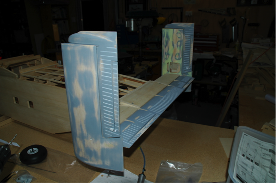
Basic fuselage construction was now complete and it was time to begin construction of the tail feathers. First step is to build the elevator. About halfway through that I realised that something didn’t look right. After some research, I realised that the kit tailplane/elevator had been altered, presumably to simplify construction. The real elevator hinge line is the same as the model, but the hinge line is at about 30% elevator chord, not at the leading edge as per the model. Essentially, the model elevator is about two thirds the area it should be. Also, the real elevator airfoil is unusual as it is basically an inverted flat bottom airfoil. I sketched a rough plan on a piece of A4 and started building. The tailplane has spruce spars because it has to support the weight of the fins at each end. 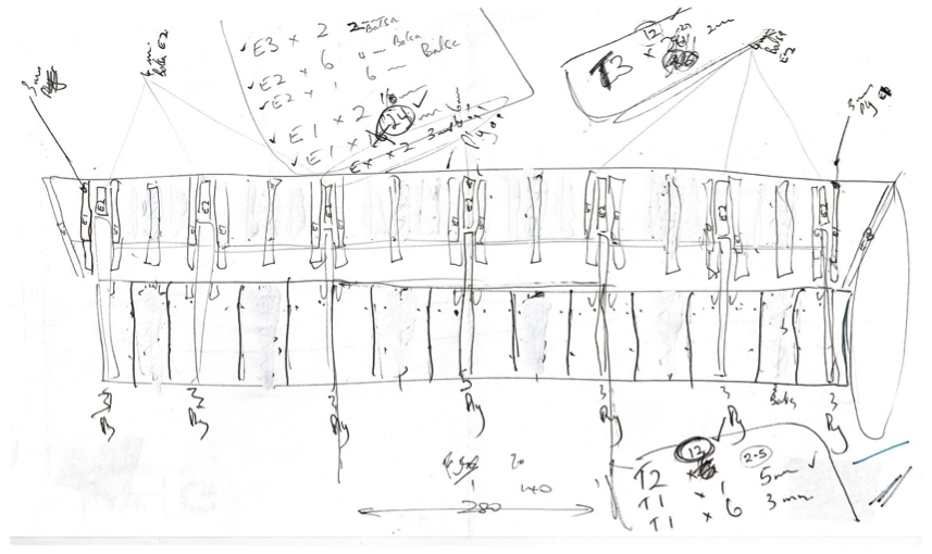
There is an aluminium tube to act as a bearing for a removable carbon tube hinge. The fins are located by three pins in a triangle arrangement. The fins are retained with a bolt. Rudders, fins and the elevator can all be removed for maintenance. The tailplane is located at the front with a couple of dowels and retained with two bolts.
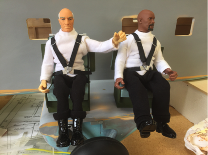
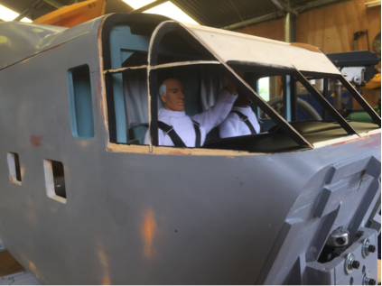
Fuselage construction is now largely done. I have added some cockpit detail and a couple of pilots. I still have to fit side windows, for which I will probably rebate around the openings to inset the window material and finish flush with the sides. Final window shape will be created by masking during finishing.
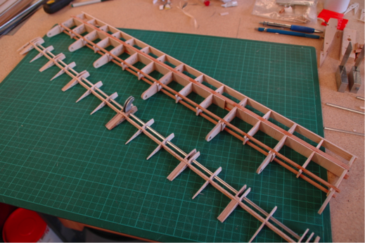
My big headache at the moment is the windscreen. It is 30 years old, yellowed and brittle. I have managed to break it in half. I am attempting to polish the areas with compound curves, and if successful, will use those pieces and new flat material to create something acceptable. Wing construction should be straight forward, but as this model has been some three years in the making so far, don’t hold your breath waiting for a maiden flight.
Mick


It all looks very impressive.
Nice build!
I am doing the same build as you (Ebersol,) upscaled to 305cm. with support of Cambria plans.
LCA made laser cut parts from drawing. Quite a job, but fun to work with.
hello friend my name is erick i am from venezuela if i am trying to make an airplane of those a skyvan, if you could help me with everything of the plane thanks my mail is Erickdurre96@gmail.com