Recently, George Carnie asked me for some details on the construction of my Fokker D-VII.
The D-VII has always been my most favorite plane, but I have been putting-off making a scale one as I am not very much into scale. Over 57 years of modeling, this is my second attempt. I did not even finish the first scale, got despondent and gave it to Kevin (the Bucker Jungmeister).
Can’t really remember when I started this one, at best guess around mid to late 2004. Obviously building has been and still is a succession of ‘all go!’ and ‘why do I bother’.
I read an article in the “flying Scale Models’ magazines of February and March 2004, got excited and started off by getting plans from RC Modeler Magazine, being under the impression that they mentioned scale!
I also ordered a set of 4 plans from the Smithsonian Institute and while waiting for them, started with the wings. Eight months later (Chinese junk must have lost its sails in a storm), I received the drawings.
Horror! There were discrepancies between the RCM plans and the Smithsonian’s. Never mind, I’ll just order Windsock Anthology one, two and three on the Fokker D-VII . They arrived and of course, since I already had built the wings, the Smithsonian matched the Windsock. (refer Murphy’s Law no 1)
The RCM wings were pretty well correct apart for the wing thickness not tapering enough and the aileron cut-outs resulting in a tapering aileron leading edge (due to the fatter ribs), a sanding block and some prayers kind of fixed the problem. Not noticeable to the untrained eye, but it still nags me.
The fuselage’s width and height, tail plane, wheel position, top wing position and a few other things needed a complete re-draw to match the Smithsonian & Winsock drawings.
I used 1/4″ spruce for framing the fuselage and locked everything together with 3 carbon pins at every junction so that the thin braided stainless steel wire used for the rigging would not cut its way through the spruce. The inner rigging was tensioned with small Graupner turn-buckles, this allowed me to square-up the fuzz which was a bit lopsided. As an excuse I can point to the fact that the real plane was also ‘tuned’ the same way.
It is at that point that I decided to go for full detailing, at least to the best of my capabilities. So due to that single spark in a brain synapse, I managed to add years of frustration!
First thing was to make the cockpit area look realistic, hard to do with 1/4″ spruce showing everywhere. I jigged the fuselage up so that it would not fall apart and removed the two top spars at the cockpit location and replaced them with some hollow carbon tube reinforced with piano wire, the wire was bent at 90 degrees at each end, sunk into the 1/4″ spruce, bound and glued. The rest of the spacers were replaced by a mix of aluminium and carbons tubing epoxied into brass T-pieces (silver soldered) at the junction points.
Luckily, I stumbled on a great web-site here where they were in the process of scratch building a full size D-VII with lots and lots of photos, including close-ups of many parts. That helped me a lot although it gave me more and more decision paths to ponder. (Ignorance is bliss!)
Cockpit area;
The following photos are the full size items to give you an idea what I aimed for.
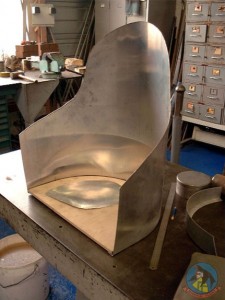 The seat was built as per original, that is; plywood base, aluminium backing with flared edges, the edges drilled then bound and covered with edging material, foam glued-on (could not find any horse hair) and finally covered with thin leather. The only thing not to scale is that the seat supports which are supposed to be able to be adjusted up or down are locked into a fixed position. The pilot can be removed since I made the seat belt fittings fully operational.
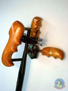 The stick; how hard can it be? Well, because the D-VII had no in-flight trims, the pilot needed a more ‘hands-on’ approach on the stick, thus in comes the offset grip with remote-throttle and machine gun triggers. The hand-grip is of course offset to the right, I suppose the pilot would have more pull strength in a straight-back pull than towards the chest. (Remember NO trims!) It also looks like if you were left-handed, you were destined for the trenches. I made all the mechanical parts of the controls fully functional and cabled like the original, I have however, locked the controls in the neutral position.
The machine guns, I ordered 2 kits from ‘Arizona Model Aircrafters’, the advert was not explicit enough for 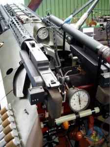 me to figure-out as to what I would receive. Naturally each kit was for 2 machine guns and it turned-out that the kits were just a heap of laser-cut bits of ply-wood, cardboard and some odd ends of aluminium tubing. A note of interest; early-on, the spent cartridges were just throw away, hence that slide visible on the left side of the gun. Later-on, a spent cartridge box was added for collection and re-use . Also note the round counter on the rear-left of the gun. The LMG (leichtes Maschinen Gewehr) 08/15 Spandau fired 7.92mm rounds at 400 rounds per minute. Firing was synchronized by a cam from the engine.
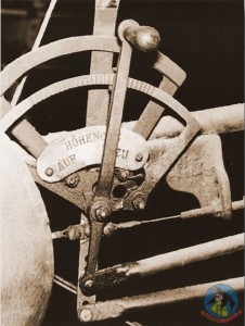 The throttle; a real dog’s breakfast of levers, rods and cables. This was the item that stopped me dead in my tracks for over a year. I just could not convince myself that I would be able to reproduce that contraption with only a jeweler’s saw, a few files and some sandpaper. Took around a week to make, I had to re-do some parts due to the fact that I got carried away during the assembly. I had to rivet the parts together and some failed under the hammering.
Now let’s digress a bit and look at the landing gear and wheels. Before starting on the landing gear, I had a decision to make, which Fokker D-VII? Some 7-800 were built and not two were alike!
Why you say? Here are the main reasons;
- There were no plans for the prototype; Fokker virtually rebuilt the plane overnight prior to THE demonstration because the plane was directionally unstable and prone to spinning. He made a small modification; lengthened the fuselage by 16 inches, new fin and rudder, shifted the upper wing and altered the aileron balance.
- Work was contracted out to three major aviation works and since there were no drawings available, they each ordered their engineers to just measure the prototype (using their poetic engineering licenses, they also made a few adjustments, without telling the opposition, of course).
- So from the beginning, we already had three different versions.
- Shortages of materials required some innovative work a-rounds;
- No radiators? How about using a truck radiator?
- Short of blue paint? Add a bit of white, still short? Add a bit more white.
- No ply-wood? Just cover it with canvas, no canvas? Leave it open, etc…
A little bit of trivia; at the end of each production line there was a boilermaker and a blacksmith station, if the parts supplied from various sub-contractors did not quite fit, they were soon convinced to behave.
On arrival at a Jasta (Jagdstaffeln), it was imperative to apply the squadron markings and of course the individual/ favorite markings of each pilot.
Obliterating factory markings became an amusing pass-time! You would think that the individualization of the Fokker D-VII was complete, how wrong you can be! A strange thing happened during the summer, D-VII’s were being shot down without any enemy in sight!
Consider this, a hot summer, a BIG hot engine, no firewall, high octane fuel, AND ammunition boxes that contained amongst other goodies, phosphorous TRACERS. Scenario = ammunition box gets hot, tracer gets hot, tracer ignites, tracer shoots through the ammunition box into fuel tank, fuel tank explodes, pilot does not complain, so big mystery.
When realization struck, out came the tin snips and mechanics became ‘louver cutter’ specialists. Still too hot? Cut some more or get rid of the paneling altogether.
Soon there were a lot of planes that were an amalgam of all the spare parts that were available at short notice, top wing from that one, wheels from that wreck, aileron from over there, etc…
So there were around 800 planes built and each one was unique. All photos were in black and white and any crew member was always standing in front of any residual markings when a picture was taken and colours were judged by interpretation of the various shades of gray or by hearsay, so much for being able to get accurate information on a plane!
I decided to use the most obscure plane available, so logically nobody can tell me that what I built is incorrect! The chosen plane was from the ‘Ostdeutsche Albatros Werke’ (OAW) factory in Schneidemuhl, was located at Nivelles in Belgium towards the end of the war and belonged to JASTA 37, that is all I know, period.
Serial numbers allocated to OAW were 2000->2199, 4000 ->4199, 4450 -> 4649 and 6300 -> 6649. I settled on 6640, this being an end-of-war late version with late markings, paneling, louvers, etc.
Once I had decide on which factory, I knew which wheel design (dual cone with canvas cover) and which mid-wheel wing construction method to use.
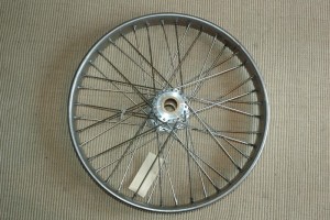 Wheel construction; A big job in making the wheels was figuring-out the 40-spokes pattern. All I had was this photo.
Hub; Brass center tube silver soldered to two pre-drilled disks which are 1/40 rotation offset from each other.
Rim; Fabricated from multiple layers of thin plywood, then hand shaped, sanded and drilled.
Assembly; Attach and drill a thin brass strip inside the tire recess of the rim. Make 40 short copper tubes flared at one end so that the flare catches the inner rim brass strip, then insert them into rim from the outside. The copper tube is just proud of the inner rim face. Mount hub and rim into a jig and line everything up. (simple to say) Insert 40 lengths of pre-bent piano wire into brass tubes, hook the bend ends into hub disk holes, silver solder piano wire to hub disks, silver solder each spoke assembly together ( spoke/copper tube/brass strip). Cut-off all excess piano wire. Cover each side of wheel with canvas. Glue-on the tire (a piece of rubber ring as used for joining concrete pipes) Repeat for other wheel.
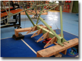 The landing gear is as per the original, the landing struts are attached to a fabricated box (one each end) that has projecting studs for the landing gear shock cords and an extended vertical cut-out to allow the free floating axle to move up and down. A fabricated aluminium box sits between the two end boxes and supports the two halves of the mid-wheel wing. The two halve wing sections are and held together with 12 bolts & nuts through joining tubes). The landing-gear axle floats in the box, supported only by the shock cords wound between the projecting struts.
Each factory had their own method of construction and installation of the mid-wheels wing. OAW used the front/back halves method with 6 bolts/nuts joining the halves at top and at the bottom. Albatros used a top/bottom clamshell setup with hinges at the front and clips at the back. Fokker had the plywood winglet in one piece with minimal access for shock-cords and other maintenance, a nightmare that was soon fixed by cutting away parts of the skin and tacking-on easily removable pieces of plywood.
